Metamaterials
Characteristics
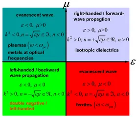
Metamaterials have created a stir as they exhibit novel electromagnetic properties on the macroscopic level net readily found in nature. Thus, their characteristics differ from the behaviour of the components they are composed of. In order to allow the definition of effective metamaterial parameters it is essential that the dimensions of the constituents are significantly smaller than the operating wavelength. Then, the wave does not face diffracion, as is the case for photonic crystals, but refraction. A "meta"-("which comes after") material is therefore tailorable to feature new properties such as perfect magnetic conductivity, frequency ranges without wave propagation (electromagnetic bandgap materials), negative refraction etc.
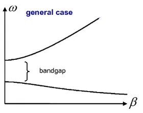
A negative refractive index is reasoned by a simultaneous negative permeability and negative permittivity. In this case, backward wave propagation occurs and the phase velocity is anti-parallel to the group velocity. The phenomenon becomes visible in the dispersion diagram leading to a negative slope in the graph plotting the propagation constant versus frequency. Then, the electromagentic field vector, the magnetic field vector and the wave vector form a left-handed (LH) oriented system in contrast to the conventional right-handed (RH) sense.
Combined Right-/Left-Handed Transmission Line
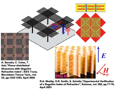
An engineering approach to metamaterials is the concept of composite right-handed / left-handed (CRHLH) transmission lines (TL) [1][2]. In this manner, many structures have been conceived enhancing the electromagnetic performance of engineered devices or even leading to unprecedented functionalities.
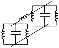
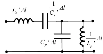
In the equivalent circuit of a CRHLH TL, which is valid for infinitesimal length of the TL, both systems are accounted for. Common elaborations try to mimic the CRLH TL EQC with lumped or distributed elements.
Realisation as Substrate Integrated Waveguide
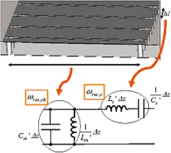
Conversely to other metamaterial realisations, this design exploits the nature of the H10rectangular waveguide mode described by the approved EQC [3]. Therefore, it is not necessary to emulate the CRHLH EQC in a man-made way. Corrugated waveguide design is another way of implementation [4], which is however by no means handy or easy to fabricate. Instead, an upgraded substrate integrated waveguide [5] serves as base with the vertical sidewalls replaced by rows of vias. By adaquate modifications, we accomplish the missing series capacitance to a considerable value. Hence, just short periodic units compared to wavelength suffice, complying well the homogeneous criterion. The periodic set-up simplifies not only the fabrication but also the analysis. According to Bloch's theorem, only one unit cell is to investigate in the analysis while periodic boundary conditions are defined. The result is a compact, light-weight, convenient to manufacture with planar printed technology waveguide architecture [6][7].
Balancing Procedure
Another benefit is the easy-to-handle balancing procedure. The transverse geometry describes the former cut-off frequency of the conventional RH waveguide. By enabling the LH feature, this cut-off frequency is now substituted by the so-called transition frequency since it denotes the continuous switch from the LH range into the RH range for a balanced composition. If balanced the previous stop in wave propagation is overcome and wave propagation is enabled throughout.
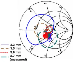
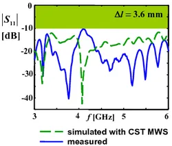
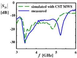
In the balanced state, the resonance frequency of the shunt circuit is identical with the resonance frequency of the series circuit. The transverse dimension prescribes the shunt resonance whereas the series resonance is to be adjusted by the longitudinal unitary length. To highlight is that the tuning parameters are decoupled from each other which enormously simplifies this procedure. Additionally, various means exist to control the effects. In the balanced condition, the charcteristic impedance becomes frequency independent [1] to observe e.g. as the reflection coefficient in the Smith chart. For this design, the balanced condition has been met with a unit length of Δl=3.6 mm. The connection to a 50 Ω microstrip line is realised by a smart tapered transition. The outcoming reflection coeffiecient (|S11|≤ 14 dB) witnesses broadband matching. In terms of an open structure, radiation is required. For this reason, the transmission coefficient is to be rather flat and low without a stop band.
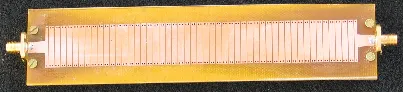
The prototype makes up a total length of 180 mm with 50 unit cells. It is mainly constituted on the low-cost dielectric FR-4 to be economical.
Dispersion Diagram
Since the H10 rectangular waveguide mode supplies the fundament for this design, operation unambiguously takes place merely in the fundamental mode. The dispersion diagram visualises the physical meaning of the complex wave solution for the Helmholtz equation. For an eigenvalue solution defined as γ=α+jβ, a real β signifies wave propagation illustrated in the diagram as a graph in dependence of the frequency. Given that the separation condition always must be fulfilled the β traveling along the metamaterial interface is related to the phase constant normal to the interface and pointing into the surrounding medium (e.g.: z0) and the free space wave number k0 for the 2 D case in the following sense:
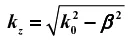
With respect to the leaky-wave antenna, effective radiation occurs in the so-called fast-wave domain if β permits a real kz. In the limit β=0, kz=k0 broadside radiation is obtained, here at 4 GHz. The light line (green in the figure) separates the fast-wave from the slow-wave domain.
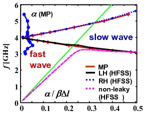
The determination of the eigenvalues, illustrated in the dispersion diagram, may be performed with a commercial eigenmode solver e.g. Ansoft HFSS. To double-check the results, the estimation technique Matrix-Pencil [8] is employed to the field data obtained by the full-wave analysis of the driven 50-cell model in CST Microwave Studio. The Matrix-Pencil algorithm further provides the attenuation constant α. The accordance can be seen in the figure.
Radiation Performance
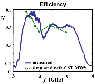
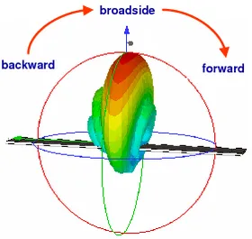
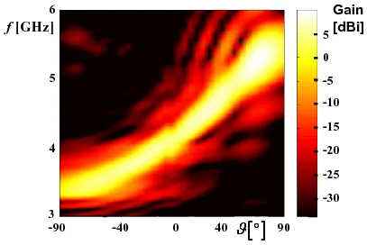
Although the low-cost lossy FR-4 substrate is utilised the efficiency reaches 50%-60%. An improvement is conceivable by using a higher-quality substrate. For broadside radiation at 4 GHz a gain of 8.64 dBi is measured and becomes maximum at 5.3 GHz with 10.15 dBi. The ample and even contiguous scanning capability by mere frequency variation is depicted in the figures. Hence, no additional phase shifters are necessary to steer the beam. To note is the remarkable gain throughout the frequencies. By the balanced CRHLH property, continuous radiation from backfire to endfire including broadside direction is attained.
![measured E-plane cuts for gain [dBi] according to IEEE definition](/fileadmin/_processed_/4/4/csm_rad_patt_61ace0d881.webp)
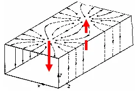
The following three figures depict a field cut in the E-plane for the three characteristic frequency ranges. The radiation behaviour is to observe in the RH range, for the broadside case and in the LH range. They are obtained from the CST MWS simulation.
References
- C. Caloz, T. Itoh, "Electromagnetic Metamaterials: Transmission Line Theory and Microwave Applications", Wiley, New York, 2005.
- A. Lai, T. Itoh, "Composite Right/Left-Handed Transmission Line Metamaterials", IEEE Microwave Mag., pp. 34-50, Sep. 2004.
- Marcuvitz, "Waveguide Handbook", McGrall-Hill, New York, 1951.
- I.A. Eshrah and A.A. Kishk, "Analysis of Left-handed Rectangular Waveguides with Dielectric-filled Corrugations Using the Asymptotic Corrugation Boundary Conditions", IEE Proc.-Microw. Antennas Propag., vol. 153, no. 3, pp. 221- 225, June 2006.
- D. Deslandes, K. Wu, "Analysis and Design of Current Probe Transition From Grounded Coplanar to Substrate Integrated Rectangular Waveguides", IEEE Trans. Microwave Theory Techniq., vol. 53, no. 8, pp. 2487 – 494, Aug. 2005.
- Y. Weitsch, T.F. Eibert, "A Left-Handed/Right-Handed Leaky-Wave Antenna Derived from Slotted Rectangular Hollow Waveguide", European Microwave Conference, Munich, Oct. 2007.
- Y. Weitsch, T.F. Eibert, "Continuous Beam-Steering Leaky-Wave Antenna Based on Substrate Integrated Waveguide", European Conference on Antennas and Propagation (EuCAP), Edinburgh, 2007.
- H. Yingbo, T. K Sarkar, "Matrix Pencil Method for Estimating Parameters of Exponentially Damped/Undamped Sinusoids in Noise", IEEE Trans. Acoustics, Speech and Signal Processing, vol. 38, no. 5, pp. 814-824, May 1990.