Near-Field Antenna Measurement and Transformation Techniques
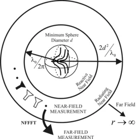
The radiation behavior of antennas is characterized by their far-field radiation pattern. The far-field region of an antenna can be assumed to hold for distances greater than 2d2/λ, whered is the diameter of a minimum sphere enclosing the antenna under test (AUT) completely. Antennas, which are large in terms of the wavelength (e.g. antennas for satellite communications, base station antennas, etc.), develop their far-field radiation characteristic in a large distance from the AUT. This influences the antenna measurement capabilities significantly since huge anechoic chambers would be required to carry out far-field measurements within controlled indoor facilities. Such anechoic chambers would be prohibitively expensive in acquisition and maintenance. An alternative approach are antenna near-field measurements in combination with a near-field far-field transformation (NFFFT). The requirements for the size of the measurement facilities are reduced considerably and results comparable to direct far-field measurements can be achieved with state-of-the-art near-field transformation algorithms.
The field distribution of an AUT can be categorized into three regions: reactive near field, radiating near field and far field. The fields consist of the same field modes and so it is possible to determine the far field of an antenna from a near-field measurement. In order to minimize mutual coupling of AUT and field probe, near-field measurements take place in the radiating near field.
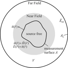
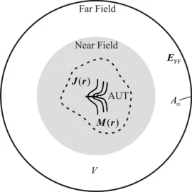
From Huygens’ principle, it is known that field values can be computed outside a closed test volume V, if the tangential fields on the test surface A are known. The sources inside the volume are represented by the field distribution on the closed surface and can be assumed zero in the following. This means if near-field values are known on a closed measurement surface, the near-field far-field transformation is straightforward by applying well-known formulas form electromagnetics.
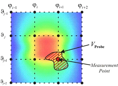
However, in a real measurement scenario it is not possible to measure electric near-field values directly. They are measured by a near-field probe and are related to the electric field strength at the measurement point via the probe output signal. These probes have a finite geometrical extension and a direction dependent receiving characteristic. In fact the field probe performs a spatial weighting of the field distribution instead of the measurement at a discrete point. Therefore it is necessary to compensate the probe influence in the formulation of the near-field far-field transformation in order to obtain accurate transformation results. This is called probe correction.
Due to the probe correction required in the transformation, a direct evaluation of Huygens’ principle is not possible since it neglects the probe influence. Therefore near-field transformation algorithms determine a set of equivalent sources, which characterizes the radiation behavior of the AUT. Different kinds of equivalent sources are feasible, e.g. spherical or cylindrical multipoles, electric and/or magnetic equivalent currents (J(r) and M(r)) or plane waves.
In our current research, near-field transformation algorithms utilizing equivalent currents and plane waves are investigated. In the near-field measurement process the radiated field distribution of the AUT is measured in the radiating near field in two polarizations. The near-field transformation algorithm relates the measured field values to the amplitudes of the equivalent sources, which are then determined in an inverse process. Once the equivalent source distribution of the AUT is known, field values at an arbitrary distance from the antenna (outside the minimum sphere) can be calculated.
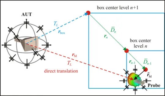
Near-field transformation algorithms translate the equivalent sources from the AUT to the field probe position in order to obtain the required relation to the measured probe output signal (as seen in the figure below for an algorithm working with plane waves). The translation is carried out by multiplying the equivalent sources with a translation operator. For techniques using spherical multipoles, these translation operators are full. Full means, every outgoing mode results in a complete set of modes at the field probe. This becomes numerically intensive for large antennas, which require a high number of equivalent sources and measurement points.
At the Lehrstuhl für Hochfrequenztechnik efficient techniques utilizing equivalent currents and plane wave representations as equivalent sources are researched. In this case the translation operators, which are well known from Fast Multipole Methods (FMM), are diagonalized so that every outgoing mode from the AUT results in a single mode at the field probe, thereby reducing the computational complexity considerably. In comparison to many standard techniques the major advantage of these algorithms is the ability to handle arbitrary measurement contours.
The probe influence on the measured near fields is compensated using a probe correction technique. Various probe correction techniques exist, with different computational costs and accuracies. The so called first order probe correction applied in spherical near-field measurements is able to compensate the influence of field probes whose azimuthal mode spectrum is limited to modes with index +- 1. An iterative extension is possible, which allows for the correction of slightly non-ideal first order probes. These techniques utilize Fast Fourier Transforms (FFT) and facilitate very efficient probe correction. Nevertheless, when higher order probes are considered or irregular measurement grids are used, FFT based methods can no longer be applied and a cost intensive full probe correction is required.
The probe correction technique, which is applied in our algorithms, simply weights the incident plane waves at the measurement point according to the far-field characteristic of the field probe. This can be done with little effort for almost arbitrary probes and arbitrary measurement contours without increasing the overall complexity of the algorithms.
For electrically larger antennas it is preferable to group several measurement points together, to create a multilevel box structure according to the Multilevel Fast Multipole Method (MLFMM) and to handle nearby measurements points in common in order to further reduce the computational complexity. The plane waves representing the AUT are translated to the boxes on the highest level only. They are further processed through the levels to the measurement points using a disaggregation and anterpolation process. Disaggregation is a simple phase shift from the box centers at the higher level to the center at the lower level or the measurement points. Anterpolation reduces the sampling rate of the plane waves on a given level and can be thought as adjoint operation to interpolation. This is possible since the spectral content of the spectrum decreases with the box size. This is the main point to obtain an algorithm with low complexity. On the lowest level, the probe correction is performed by weighting the plane waves with the probe’s far-field pattern. With this multilevel algorithm it is possible to obtain an overall complexity of the transformation of O(N logN), N being the number of measurement points.
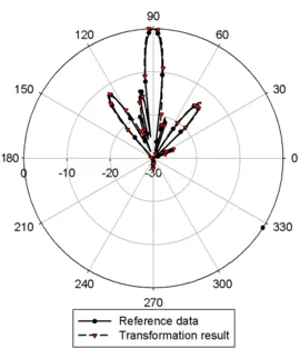
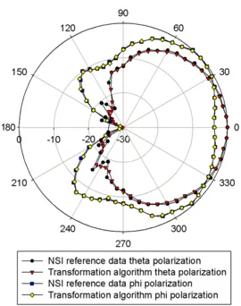
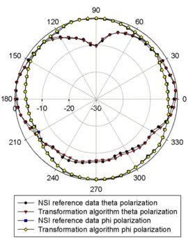
In the following results of our plane wave based near-field transformation algorithm are shown for the measurement of a patch antenna, mounted on a circular ground plane. The field distribution of the AUT was measured by an open-ended waveguide probe (OWG) of type WR430 at a frequency of 2.3 GHz using a spherical NSI near-field measurement system. The transformation results show a good agreement to the reference, which was obtained by a NSI near-field transformation algorithm.
The near-field data as well as the transformed far-field pattern were provided by Fraunhofer Institute for Integrated Circuits IIS.
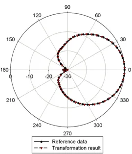
Further results are shown for the near-field measurement of a Kathrein base station antenna of type 742 445. The AUT has a height of 1.3 m which equals 8.3 λ at the measurement frequency of 1.92 GHz. The measurement is carried out again using an OWG probe of type WR430 and a spherical NSI near-field scanner. An NSI near-field transformation algorithm was used for reference.
The near-field data as well as the transformed far-field pattern were provided by KATHREIN-Werke KG.